Three-phase flow metering for Coriolis research, Advanced Instrumentation Research Group
Three-phase flow metering
An overview of our new commercial three-phase flowmetering technology based on Coriolis mass flow metering.
We are currently working on a new three-phase metering system, which is being described in the literature [1] and offered as a commercial product [2].
A desirable extension to our two-phase work is to provide three-phase metering for the upstream oil and gas industry, where the three phases are water, oil and gas respectively. To a first approximation, this can be treated as a two phase (liquid/gas) problem, where the density of the liquid varies with the water cut. Here water cut is taken to represent the proportion by volume of the water in the total liquid. Thus if the water cut is 0%, the liquid is pure oil (irrespective of GVF) and if the water cut is 100%, the liquid is pure water (irrespective of GVF). In practice it is now possible to measure the water cut of a three-phase mixture with reasonable accuracy using a commercial water cut meter, and it is further possible to include water cut variation in the modelling of the mass flow and density errors; accordingly a three-phase metering system based on Coriolis mass flow metering has been developed.
A three-phase mixture can be specified in a number of ways; two are used frequently here. The first is to specify the mass flows of the oil, water and gas components; given the low operating pressures we work with, the oil and water flows are stated in kg/s, while the gas flow rate is stated in g/s. The alternative description is to specify the total liquid flow rate (usually in kg/s), water cut (between 0% and 100%) and GVF (from 0% up to 50% and beyond). Where it is assumed that the density of each phase is known along with temperature and pressure conditions, and that there is no slip between phases, it is straightforward to convert from one of these specifications to the other. Typically, the first description (mass flows of each phase) is used for specifying the accuracy of final results, while the latter description (liquid flow/water cut/GVF) is used for describing experimental conditions, particularly during model development.
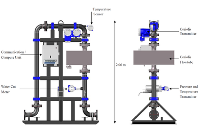
Fig. 1: Three-Phase Skid design
Figure 1 shows the design of the Skid. The pipework dimensions and internal diameter (50mm) are the same for a range of Coriolis meter inlet diameters from 15mm to 50mm. Adaptors are provided on the down-leg to accommodate flow tubes smaller than 50mm diameter; a new skid design with 80mm flow tube and pipework has recently been developed.
In addition to the Coriolis flow tube and transmitter, the instrumentation on the skid consists of a water cut meter and a pressure and temperature transmitter. The latter reads the pressure at the inlet to the Coriolis meter and the temperature of an RTD (resistance temperature detector) sensor in a thermal well, positioned at the top of the skid. The Communications / Compute Unit acts as a communication master for all the devices, using the Modbus RTU industrial communications protocol, commonly used in the oil and gas industry. The compute unit performs three-phase flow measurement calculations based on the data received, provides a user interface (for providing, for example, gas and fluids density information) and also carries out data archiving. Real-time data is available to the user’s data acquisition system via a Modbus interface, with an update rate of 1 second.
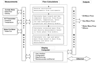
Fig. 2: Net Oil and Gas Skid Hardware/Software Architecture
The Hardware/Software architecture of the Skid is shown in Figure 2. The Display Computer provides three communication interfaces: an internal Modbus for the Skid instrumentation, an external Modbus interface to provide final measurement values to the user, and an Ethernet interface to enable remote configuration, monitoring and archival data retrieval. The Display Computer further provides a touch screen user interface to enable local configuration, data display, etc.
A formal series of trials were carried out on a 50mm Skid in January 2012 at TUV-NEL’s three-phase flow facility. The intention was to demonstrate compliance with the measurement performance requirements of the Russian Standard GOST 8.165, which has the following key specifications:
- Total liquid flow accuracy requirement ± 2.5%
- Total gas flow accuracy requirement ± 5.0%
- Total oil flow accuracy requirement dependent upon water cut:
- For water cuts less than 70%, oil accuracy requirement ± 6.0%
- For water cuts between 70% and 95%, oil accuracy requirement ± 15.0%
- For water cuts above 95%, no oil accuracy requirement is specified, but an indication of performance may be given.
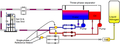
Fig. 3:Three-phase test setup at NEL
Figure 3 shows the Skid positioned in the three-phase test facility at TUV-NEL. The separator system provides water and oil streams, while a liquid nitrogen store is used to supply the test gas. Each phase is metered separately, before being combined and passed through the skid. For each experiment performed, steady conditions were established for the desired oil, water and gas flow rates, and then the reference single phase measurements was compared with the outputs of the Skid averaged over a fixed duration. During the final tests a 300s duration was used, the minimum advised by NEL for formal trials. During the formal trials the operating pressure at the Skid inlet was typically 350 kPa, while the operating temperature ranged between 35 °C and 44 °C.
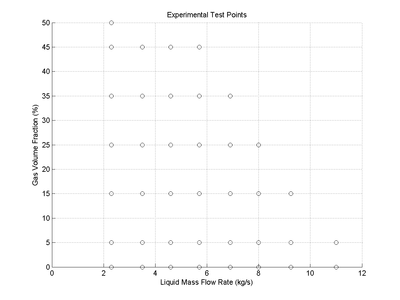
Fig. 4: NEL experimental test points - GVF vs. liquid flow rate
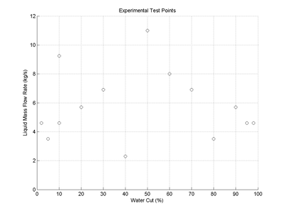
Fig. 5: NEL experimental test points - liquid flow rate vs water cut
The test matrix is shown in Figures 4 and 5. A total of 75 tests were carried out. Figure 4 shows the nominal GVF and mass flow rates used for each test; in practice, the recorded values varied within a few percent from the nominal, due to the limited accuracy of the experimental flow control. The total (water + oil) liquid mass flow rates range from 11kg/s down to 2.3kg/s. The maximum GVF decreases as the liquid mass flow rate increases, reflecting a practical limitation on the pressure drop across the Skid of approximately 1.5bar. Figure 5 shows the mass flow and water cut values used for the tests. Water cuts were tested in steps of 10% between 10% and 90%, with further tests at 2%, 5%, 95% and 98% water cuts. Tests on pure water or pure oil were not possible given the low levels of cross-contamination in the water and oil supplies from TUV-NEL’s separator system. This cross-contamination was, however, monitored and included in the calculation of Skid errors and system uncertainties.
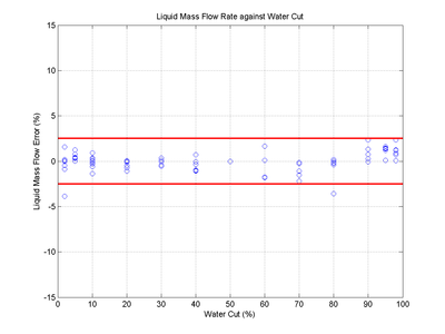
Fig. 6: NEL experimental results - liquid flow rate errors
Figures 6 – 8 give a summary of the results obtained in these test trials. Figure 6 shows the total liquid flow errors against water cut. The total liquid flow performance is similar across all water cuts, 97% of the points fall within the GOST specification of ±2.5%, and all points fall within ±4%.
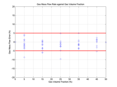
Fig. 7: NEL experimental results - gas flow rate errors
The results for the gas mass flow rate are shown in Figure 7. Again the results fall substantially within the GOST specification, with 93% of the test points falling within the ±5% limit. As discussed above, the GOST standard specifies a maximum oil error which varies with water cut. For water cuts below 70%, the permitted oil mass flow error is ±6%; between 70% and 95% water cut, the oil mass flow error limit is ±15%; and above 95% water cut, no oil mass flow error limit is specified. As shown in Figure 8, all test points match this performance requirement
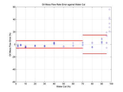
Fig. 8: NEL experimental results - oil flow rate errors
References
[1] Henry, MP, Tombs, MS, Zamora, ME, Zhou, FB. “Coriolis mass flow metering for three-phase flow: A case study”, Flow Measurement and Instrumentation, 30(2013), pp 112–122.
[2] http://iom.invensys.com/EN/Pages/IOM_NetOilandGasSolution.aspx