Static Notch Filtering for Prism Technology, Advanced Instrumentation Research Group
Static Notch Filtering
In Prism Signal Processing, Prisms may be added to the signal path in order carry out specific tasks. One simple example is static notch filtering, whereby one or more Prisms are used to notch out one or more specific frequencies.Typically for filtering purposes only a single Prism output (Gsh or Gch) is used.
This effect is most simply achieved by creating a Prism with h = 1, and m equal to the desired notch frequency. Note that all higher harmonics of m are also notched. If this is not desired, then the technique of dynamic notch filtering can be used to remove a single frequency only.
A simple illustration of static notch filtering can be provided by considering the common problem of mains noise suppression. In this case, the frequency of the mains is known and fixed (50 Hz in the UK), and higher harmonics of this frequency are also to be removed.
Two difficult examples are given below, where the mains noise amplitude is the same as that of the signal to be tracked. In the second example the level of white noise is also high.
A simple Prism-based scheme for eliminating mains noise is shown below.
![]()
In this case two Prisms act as a prefilter, each with m = 50 Hz. These serve to suppress both the mains frequency (and harmonics) and the white noise at higher frequencies. The Deep Signal Tracker (DST) is another Prism-based tracker which generates frequency / phase / amplitude estimates on a sample-by-sample basis for the filtered signal.
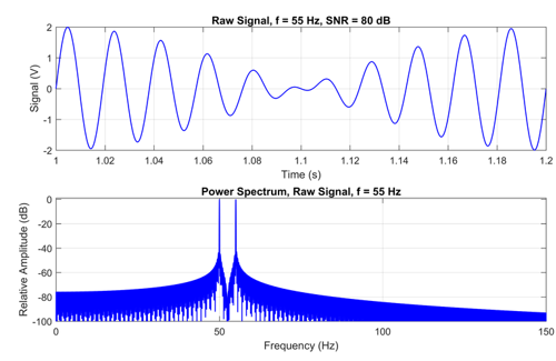
In the first example, the signal-to-noise ratio is 80 dB, but the signal to be tracked is at 55 Hz, close to the mains frequency of 50 Hz. A plot of the raw signal and its spectrum is shown below.
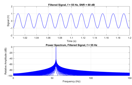
The two two Prisms acting as a notch filter succeed in removing the mains signal while leaving the desired signal intact. The gain and phase of the notch filter Prisms at the desired signal frequency are readily calculated, so the pre-filter amplitude and phase can be obtained after the filtered signal has been tracked.
The filtered signal is shown below.
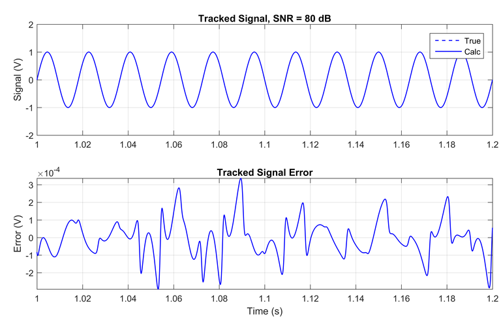
The DST tracks the resulting signal. Pre-filter compensation is applied to the amplitude and phase results to estimate the properties of the original, pre-filter signal, but with the mains noise removed. The results are shown below, where the 'Tracked' signal is composed from the calculated amplitude and phase. A good match is achieved, with most errors falling within +/- 3e-4V compared with a nominal signal amplitude of 1 V.
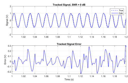
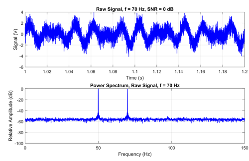
The second example is similar to the first, except the signal to be tracked is at 70Hz and the signal-to-noise ratio is only 0 dB. The original signal is shown below.
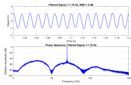
The filtered signal is shown below:
The resulting tracked signal is compared with the original component in the graph below.